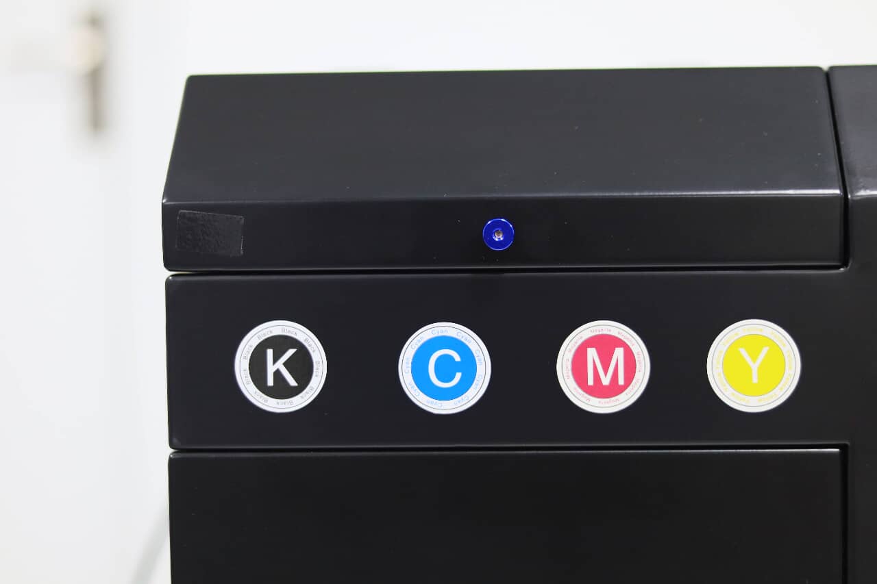
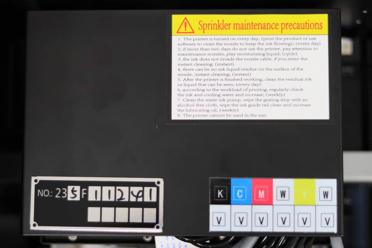
The carriage cover allows visibility of the serial number of the carriage board and the configuration of the ink setup. In this model, we observe that color and white share one print head, while varnish is allocated its own—this underscores the importance of varnish in UV DTF printing.
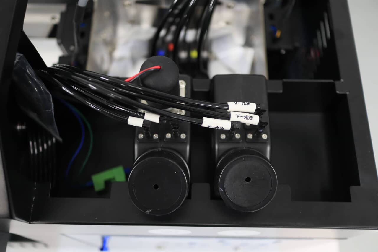
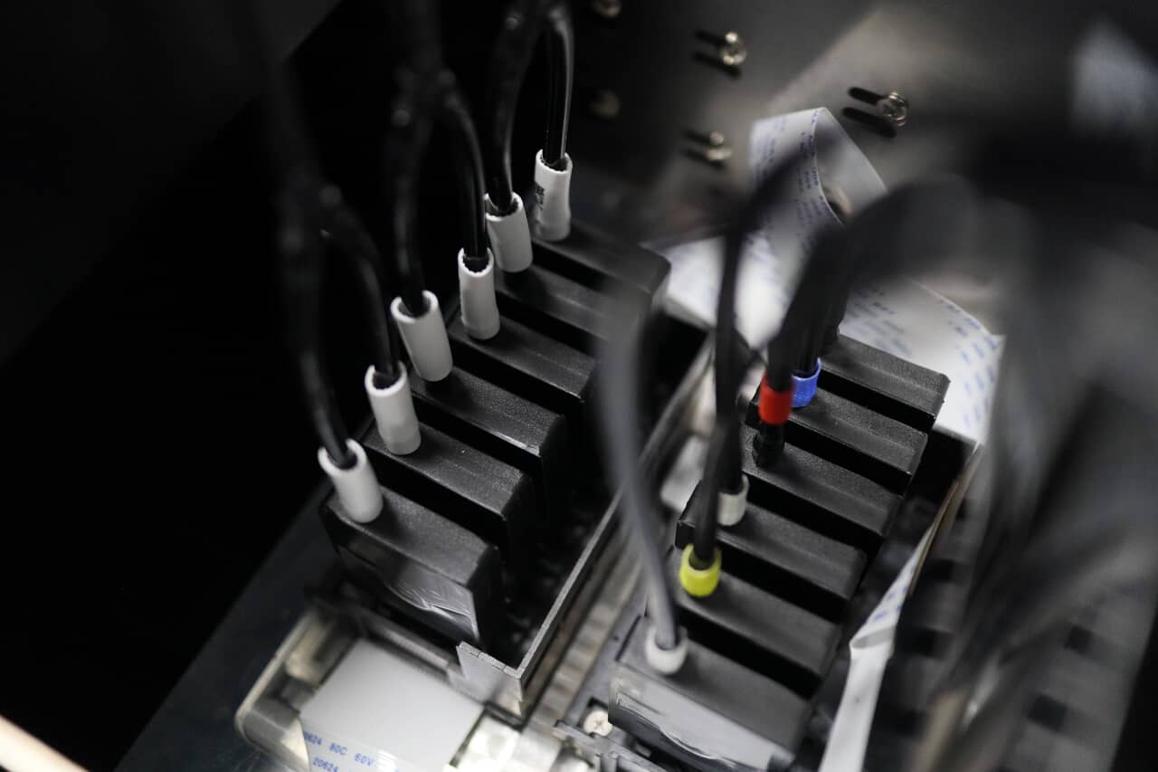
Inside the carriage, we find the dampers for the varnish and for the color and white inks. The ink flows through the tubes into these dampers before reaching the print heads. The dampers act to stabilize the ink supply and filter out any potential sediment. The cables are neatly arranged to maintain a tidy appearance and prevent ink droplets from following the cable into the junction where the cables connect to the print heads. The print heads themselves are mounted on a CNC-milled print head mounting plate, a component crafted for utmost precision, robustness, and strength.
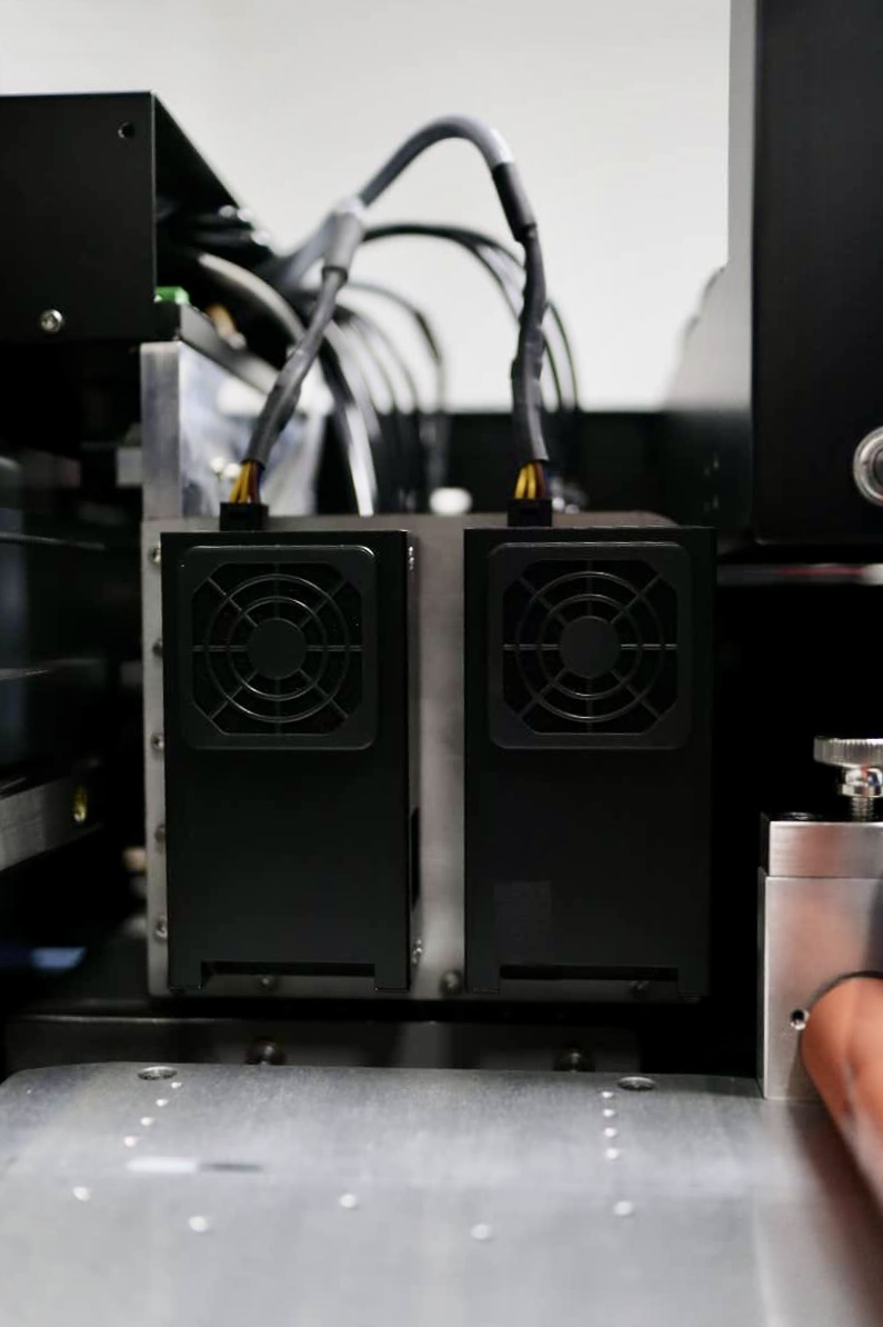
On the sides of the carriage are the UV LED lamps—there is one for varnish and two for color and white inks. Their design is both compact and orderly. Cooling fans are utilized to regulate the temperature of the lamps. Additionally, the lamps are equipped with screws for power adjustment, providing flexibility in operation and the ability to create different printing effects.
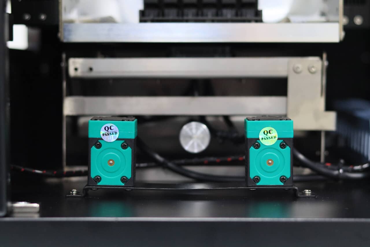
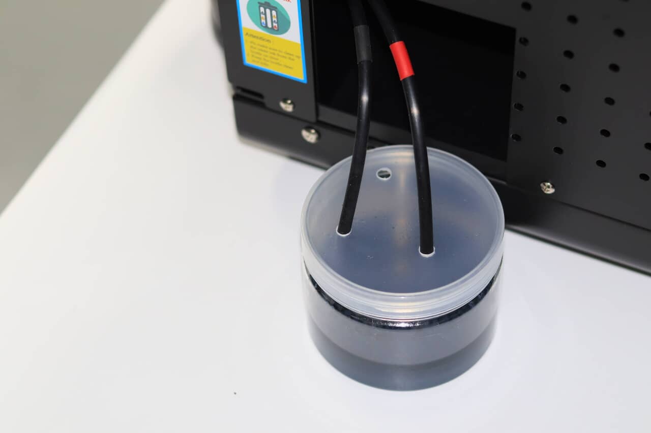
Below the carriage is the cap station, mounted directly underneath the print heads. It serves to clean and preserve the print heads. Two pumps connect to the caps that seal the print heads, directing waste ink from the print heads through the waste ink tubes to a waste ink bottle. This setup allows for easy monitoring of waste ink levels and facilitates maintenance when nearing capacity.
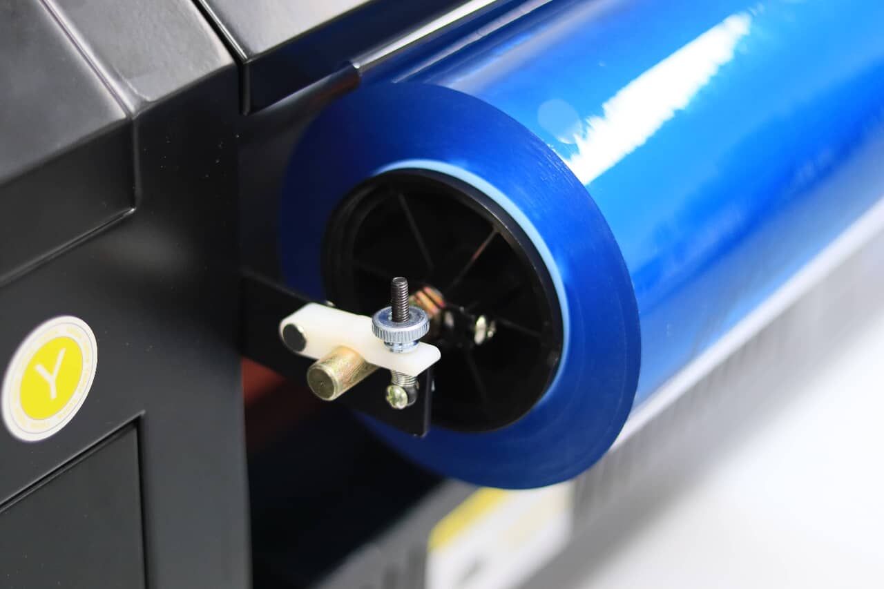
Moving on to the lamination process, we first encounter the film rollers. The lower roller holds film A, while the upper roller collects the waste film from film A.
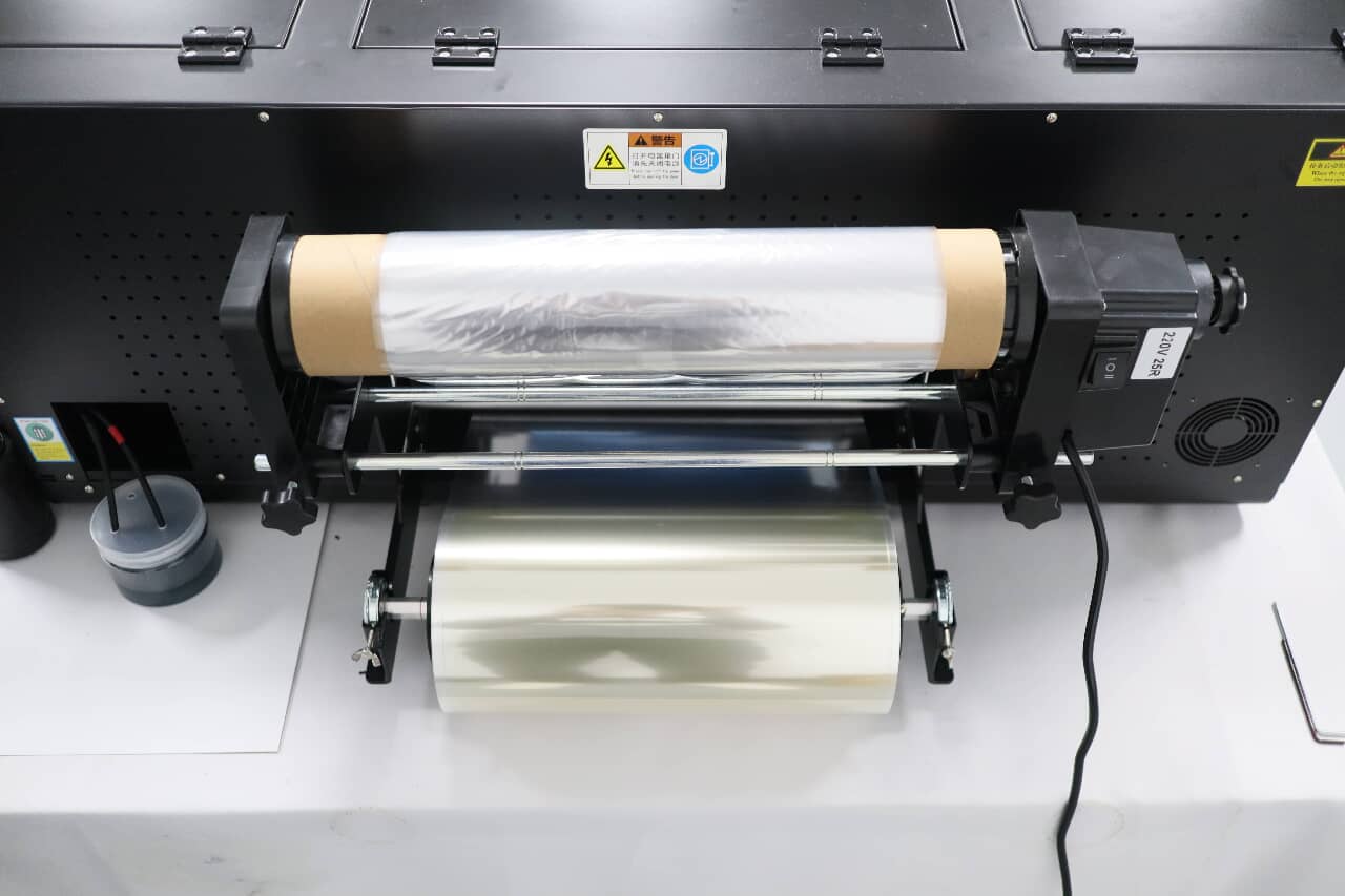
The horizontal positioning of film A can be adjusted by loosening the screws on the shaft and shifting it either right or left as desired.
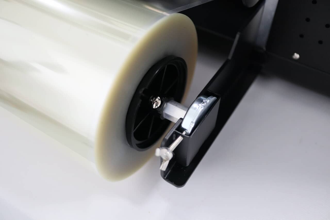
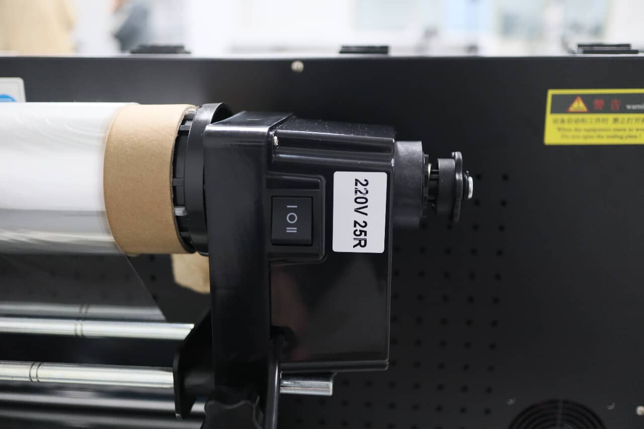
The speed controller dictates the film's movement with a single slash indicating normal speed and a double slash for higher speed. The screws on the right end adjust the rolling tightness. This device is powered independently from the main body of the machine.
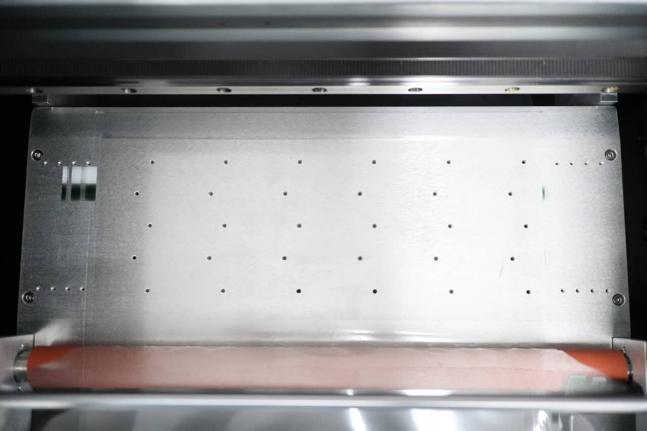
The film A passes over shafts before reaching the vacuum suction table, which is perforated with numerous holes; air is drawn through these holes by fans, generating a suction force that securely adheres the film to the platform. Positioned on the front end of the platform is a brown roller, which not only laminates films A and B together but also features a heating function to facilitate the process.
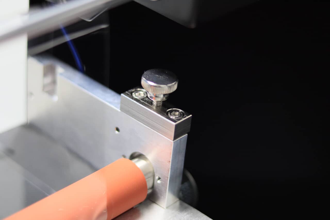
Adjacent to the brown laminating roller are screws that allow for height adjustment, which in turn determines the lamination pressure. Correct tension adjustment is critical to prevent film wrinkling, which can compromise sticker quality.
The blue roller is designated for film B installation.
Similar to the mechanism for film A, film B can also be installed in the same manner. This is the endpoint for both films.
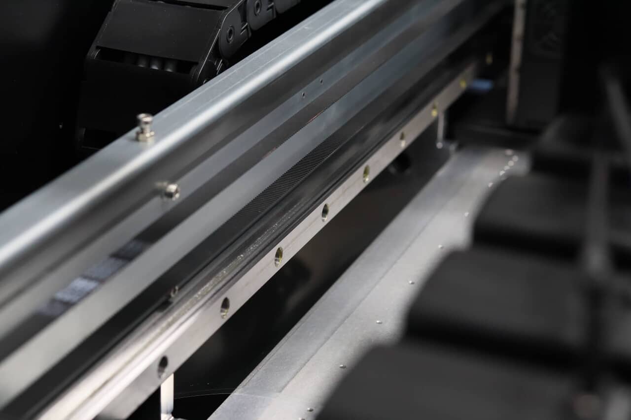
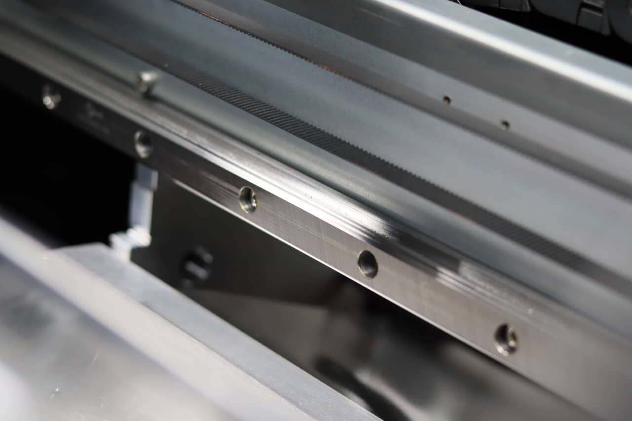
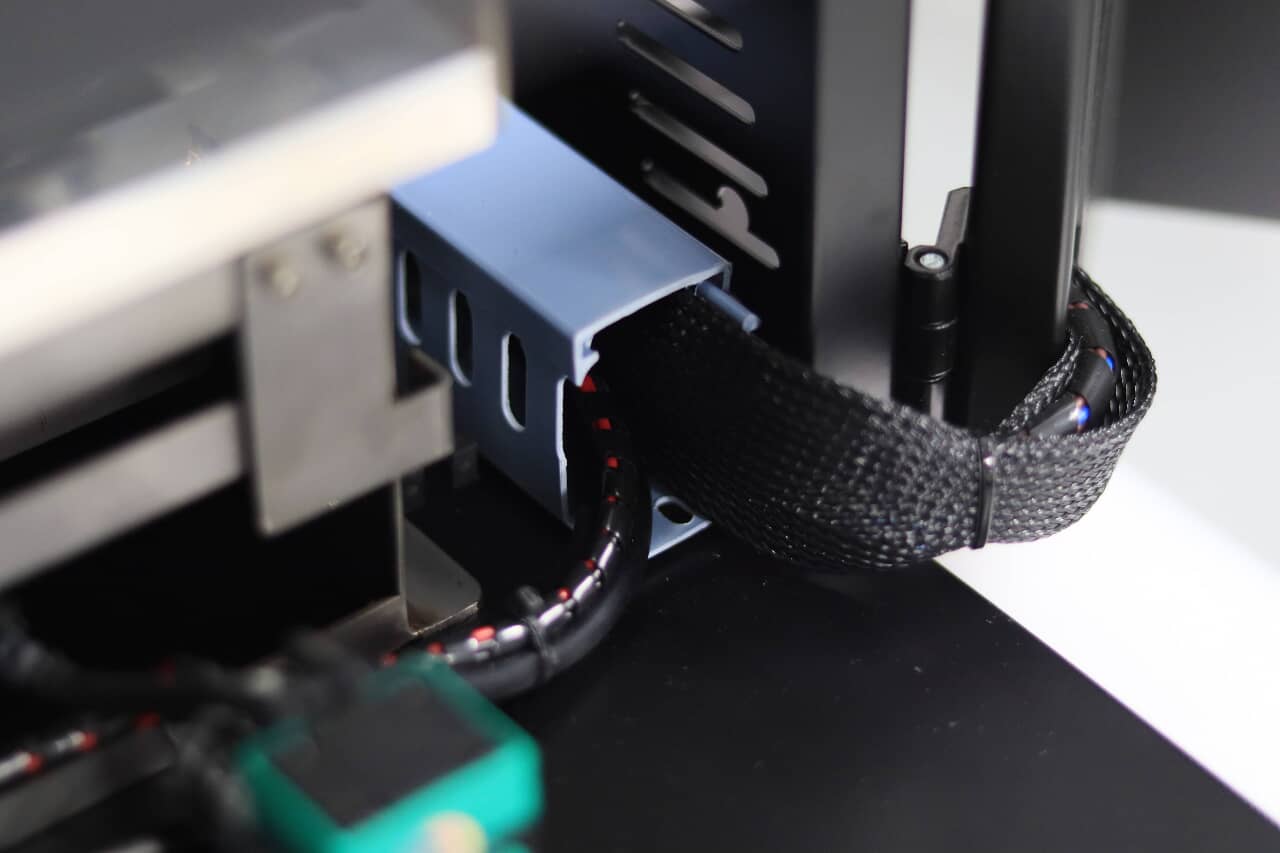
Turning our attention to the rest parts like mechanical components, we have the beam that supports the carriage slide. The beam's quality is instrumental in determining both the printer's lifespan and its printing precision. A substantial linear guideway ensures accurate carriage movement.
The cable management system keeps wires organized, strapped, and wrapped in a braid for enhanced durability and a longer lifespan.
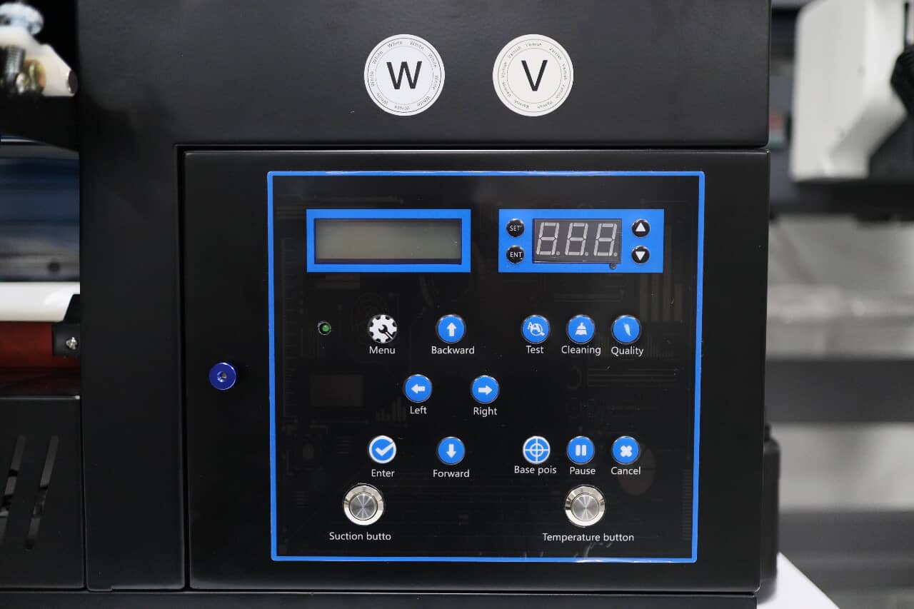
The control panel is the printer's command center, equipped with various buttons: 'forward' and 'backward' control the roller, while 'right' and 'left' navigate the carriage. The 'test' function initiates a printhead test print on the table. Pressing 'cleaning' activates the cap station to clean the printhead. 'Enter' returns the carriage to the cap station. Notably, the 'suction' button activates the suction table, and 'temperature' controls the roller's heating element. These two buttons (suction and temperature) are typically left on. The temperature setting screen above these buttons allows for precise temperature adjustments, with a maximum of 60℃—commonly set to approximately 50℃.
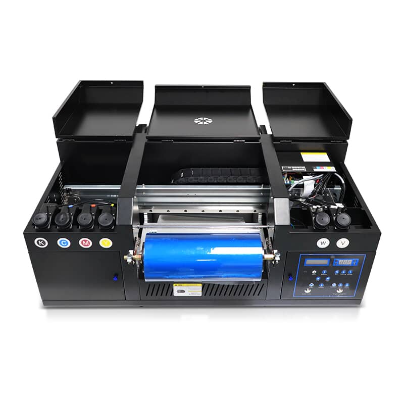
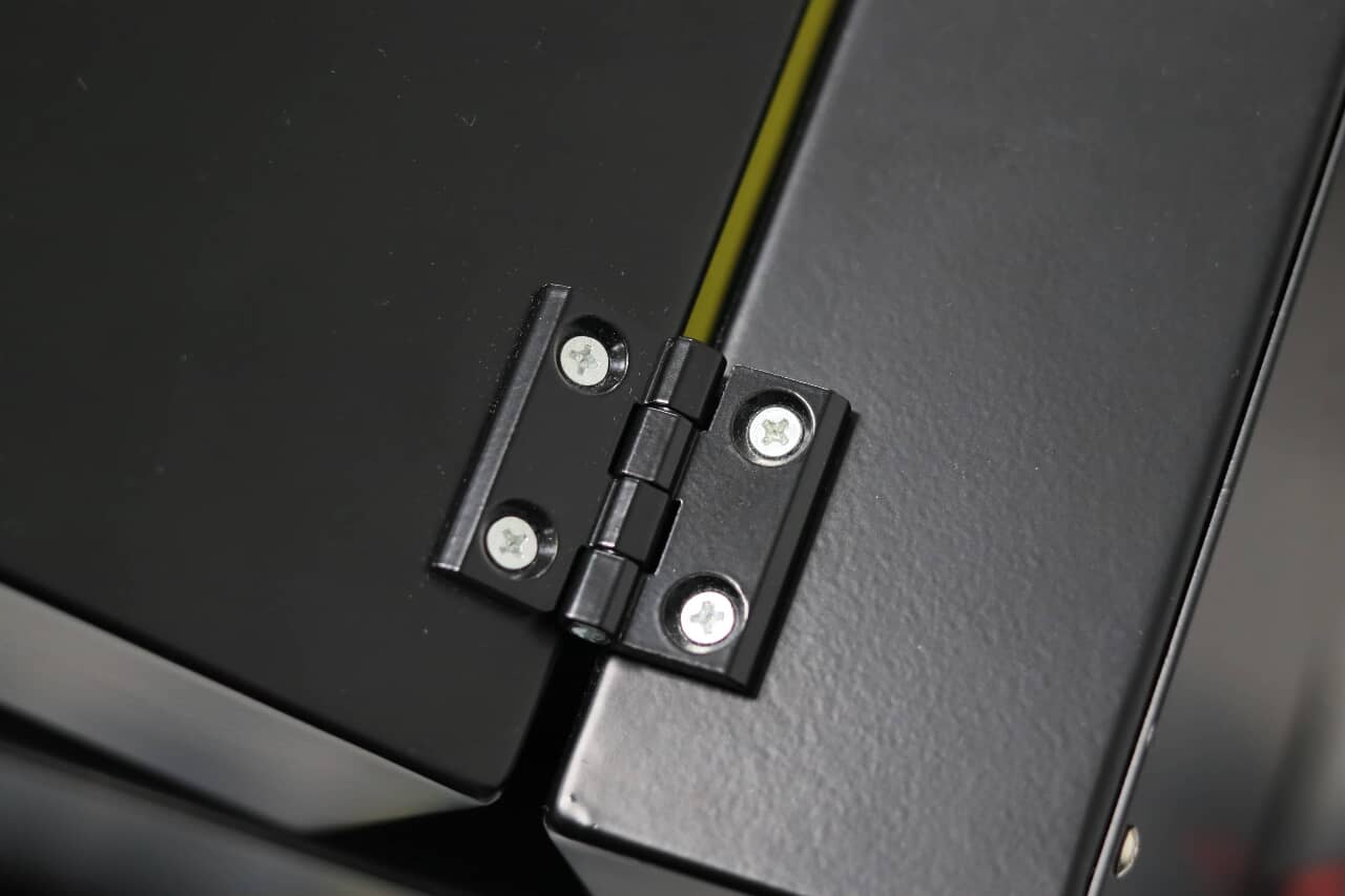
The UV DTF printer boasts a sophisticated design featuring five hinged metal shells, enabling effortless opening and closing for optimal user access. These movable shells enhance the printer's functionality, offering easy operation, maintenance, and clear visibility of internal components. Engineered to minimize dust interference, the design maintains print quality while keeping the machine's form compact and efficient. The integration of the shells with high-quality hinges to the printer's body encapsulates the careful balance of form and function.
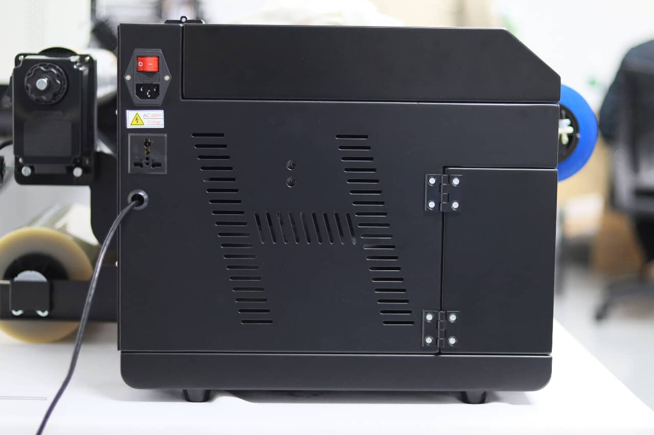
Lastly, the left side of the printer houses the power input and includes an additional outlet for the waste film rolling device, ensuring efficient power management across the system.
Post time: Dec-29-2023